


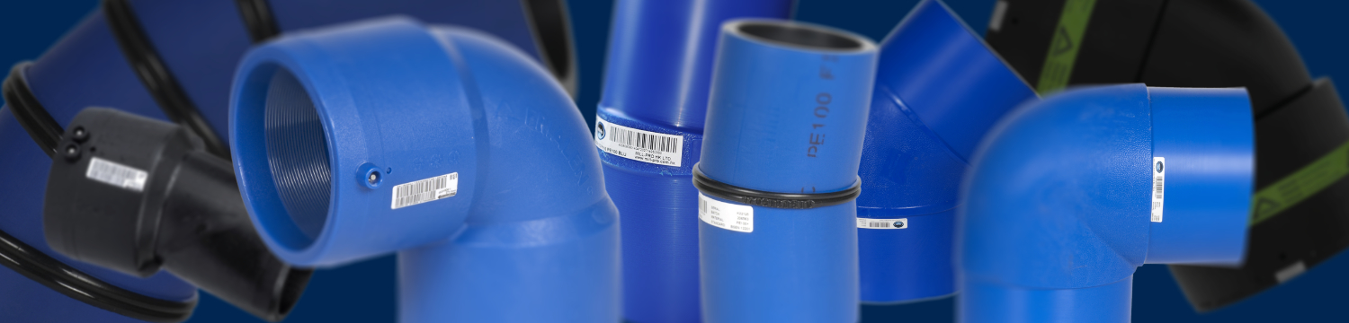
Mill-Pro offers a wide range of standard elbows and custom made bends in angles from 1º to 90º in both Blue and Black including:
- Moulded electrofusion elbows
- Moulded spigot elbows
- Segmented bends
- fabricated elbows
Moulded electrofusion elbows: in standard angles, used for smaller diameter pipelines (≤ 180 OD) with a radius of r = ~ 0.5xOD
Moulded spigot elbows: in standard angles ≤ 315 OD, with a radius of r = ~ 0.5xOD. Black injection moulded spigot elbows are available up to DN/OD 400, generally not listed for water supply as the Minimum Order Quantity (MOQ) makes their use uneconomic and WSD requires segmented bends to be used in sizes >dn 315. Black moulded elbows can be found in our wastewater section here.
Segmented bends: factory-fabricated from Blue, Black or Purple Pipe, these are available in any size and angle with the minimum radius determined by the number of mitres, generally r = 2.5xOD. Larger radii may be problematic in tight installations, so fabricated elbows can be used.
Fabricated Elbows: are a compact elbow machined from hollow bar with welded spigots and r = ~ 0.5 x OD. They are custom made in any size ≥ dn355 in any angle from 1º to 90º See here for more information.
Segmented bends
These are fabricated to BS EN 12201-3 Annex B.3, made by cutting pipes on an angle (cut angle), rotating one of the cut ends 180º and welding the angled segments back together. See Fig. 1 below. Because the cut angle is >90º to the pipe axis, the cross-sectional area of the pipe bore increases as the angle increases. The greater the angle, the greater the internal cross-sectional area at the weld. So the internal pressure is now acting on a greater internal cross-sectional area at the welded joint, however, because the pipes wall thickness (SDR) remains unchanged, the thickness of the pipe is now insufficient to maintain the original pressure rating.
Therefore the segmented bend may now be subject to a pressure de-rating factor. The amount of de-rating depends on the cut angle, the greater the angle, the greater the internal cross-sectional area and the greater the de-ration required. See Fig. 2 below.
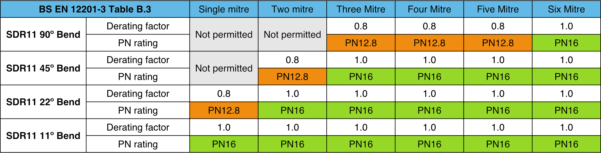
BS EN 12201-3 Annex B, B.3 Segmented bends, Table B.3, states: Bends with a cut angle ≤ 7.5º do not need de-ration. Cut angles > 7.5º but ≤ 15º must be de-rated to 0.8x the pipes original rating (20% de-ration). Cut angles > 15º are not allowed under the standard. To maintain cut angles ≤7.5º additional mitres are required. See table below
As an example: If we cut a pipe at a 15º angle to the pipe axis, rotate one half of the cut 180º around the pipe axis and then weld the cut segments back together, we create a 30º mitre joint. If a 90º bend was being fabricated, you would repeat this three times with space in between each 30º mitre to create a '3 mitre 90º bend' (See image below, 3 x 30º mitres = 90º bend). This bend has pipe cut angles of 15º. Referring to Annex B, a cut angle of >7.5º but ≤ 15º must have a de-rating factor of 0.8x applied to the original pipes PN rating.
Therefore a 90º fabricated bend fabricated with three 30º mitres cut from PN16 pipe is: PN16 x 0.8 gives a MOP (Maximum Operating Pressure) of PN12.8. Bends with 30º mitres have cut angles that are 15º, and according to Annex B3 must be de-rated. The bends new pressure rating of PN12.8 no longer matches the original pipes rating of PN16. Installing a PN12.8 bend in a PN16 water network, de-rates the entire water network to PN12.8, so this is not a solution.
There are two solutions. One is to manufacture fabricated bends from a thicker pipe (say PN20 SDR 9 pipe) with 3 x 30º mitres (not 6x mitres). This creates an undesirable internal step in the pipeline where the PN20 bend joins the PN16 pipe, however, this can be overcome with a machined internal taper at each spigot end of the bend. It still creates a reduced bore through the bend that should be considered.
The prefered way according to the BSEN standard is to manufacture the fitting from the same PN16 pipe and increase the number of mitre joints in the bend from three to six, so 6 x 15º mitres, the maximum cut angle is now ≤7.5º and according to the standard, a de-ration factor of 1.0x is applied (i.e: no de-ration of bends with 7.5º cut angles is required).
Refer to Fig.3 to see what fabricated bend designs maintain full pressure ratings according to BS EN 12201-3, Table B.3.
Fig.1
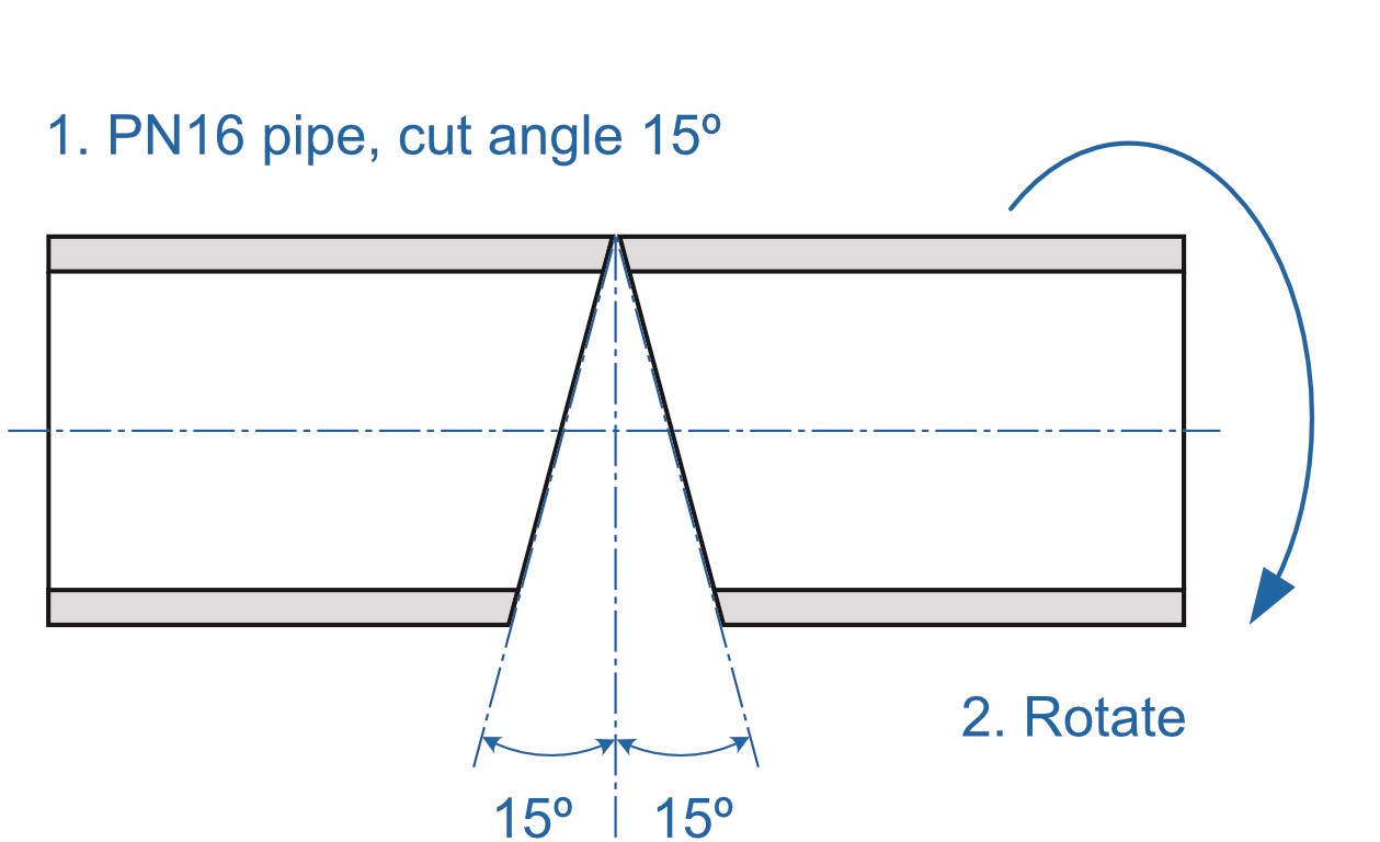
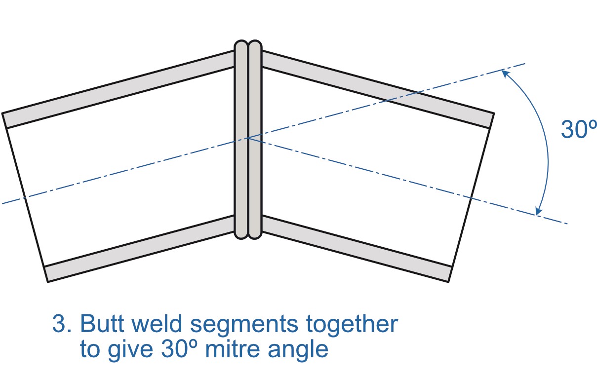
Fig.2

Fig. 3