

Curved Sewers
The use of curved sewers is common practice in many countries to reduce the requirement for Manholes when a change in direction is required. Experience has demonstrated that blockages in gravity PE pipelines lines are extremely uncommon. Guidance about the radius of curvature, types and quantity of bends used between manholes were developed by various Authorities, their use of bends has reduced the number of manholes in non entry sewers and stormwater lines by up to 75%! This reduction provides authorities enormous cost reduction in both installation and ongoing maintenance costs.
Specifications for curved PE sewers generally follow the theory
- The bend radius increases as the bend angle increases
- Limits on the number of bends installed between manholes.
For Hong Kong, the DSD Appendix 5A Table 5A-7 states:
| Angle | Radius | Number of segments in fabricated bends >500 DN/OD |
| ≤ 22° | r = ≥ 4 x pipe DN/OD | ≥ 3 |
| > 22° but ≤ 45° | r = ≥ 7 x pipe DN/OD | ≥ 4 |
| >45° | r = ≥ 10 x pipe DN/OD | ≥ 6 |
Below is an example of curved sewer specifications issued by Auckland City (New Zealand), Infrastructure Design Standard issued in 2009 - Refer Clause 6.7.4 IDSM Section 6 Wastewater
Bend Types
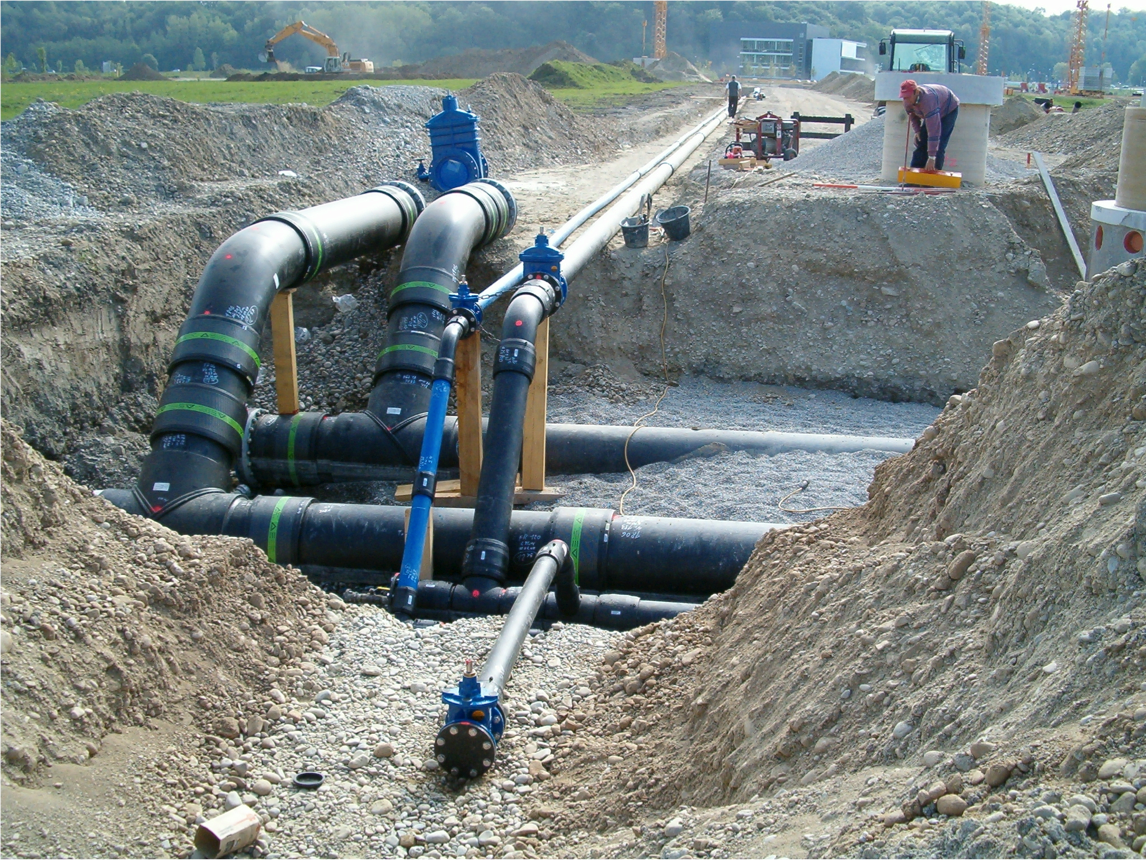
Swept bends: For bends installed horizontally in a gravity line, sizes up to DN/OD 500 should be swept type as they do not have internal welds or flat angular surfaces and offer a completely smooth bore as described in BS EN 12201-3 Annex B.4. See examples of such bends used in wastewater in Germany. Fig 1 below.
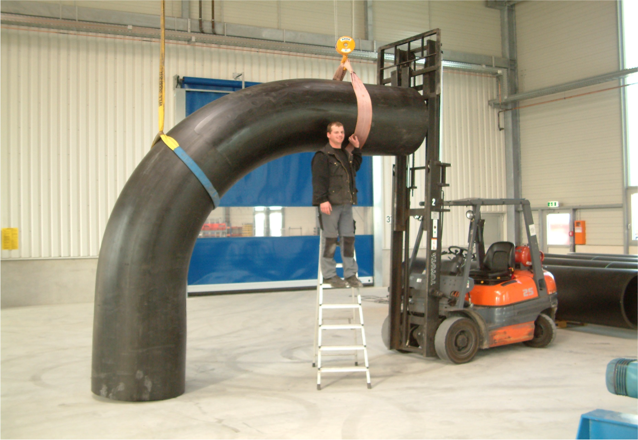

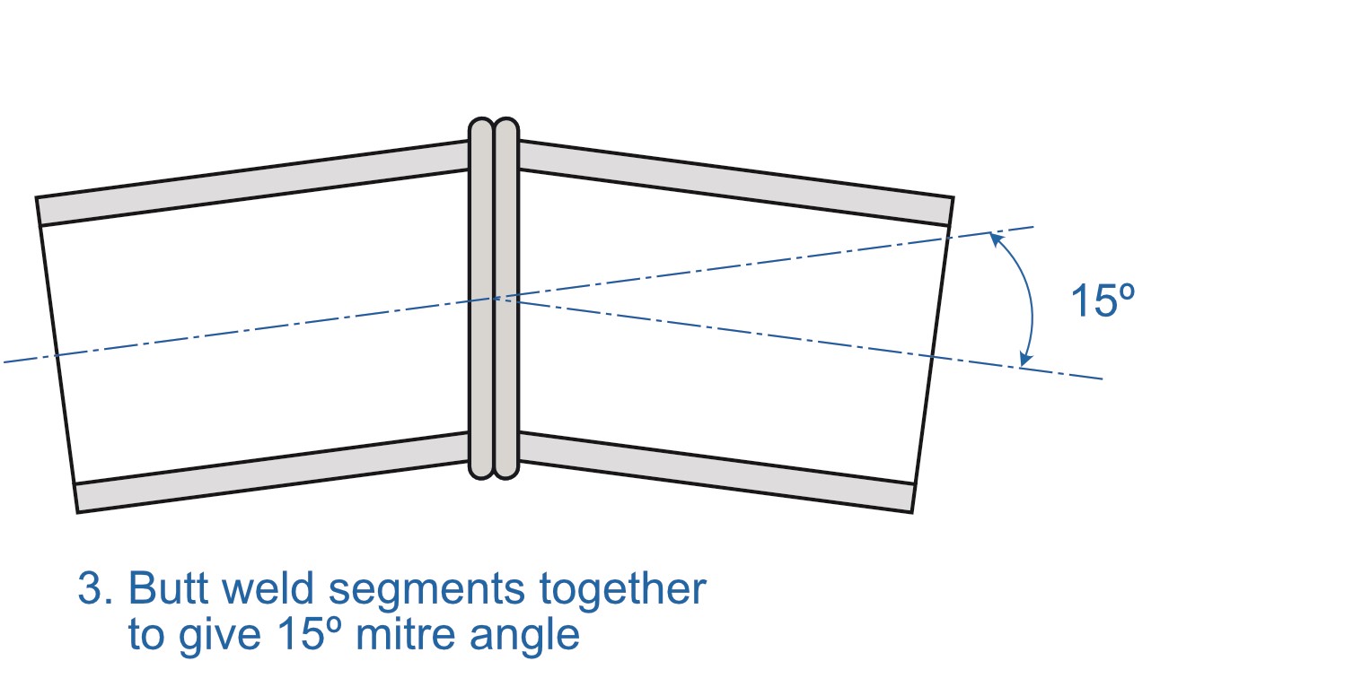
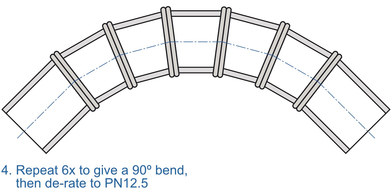
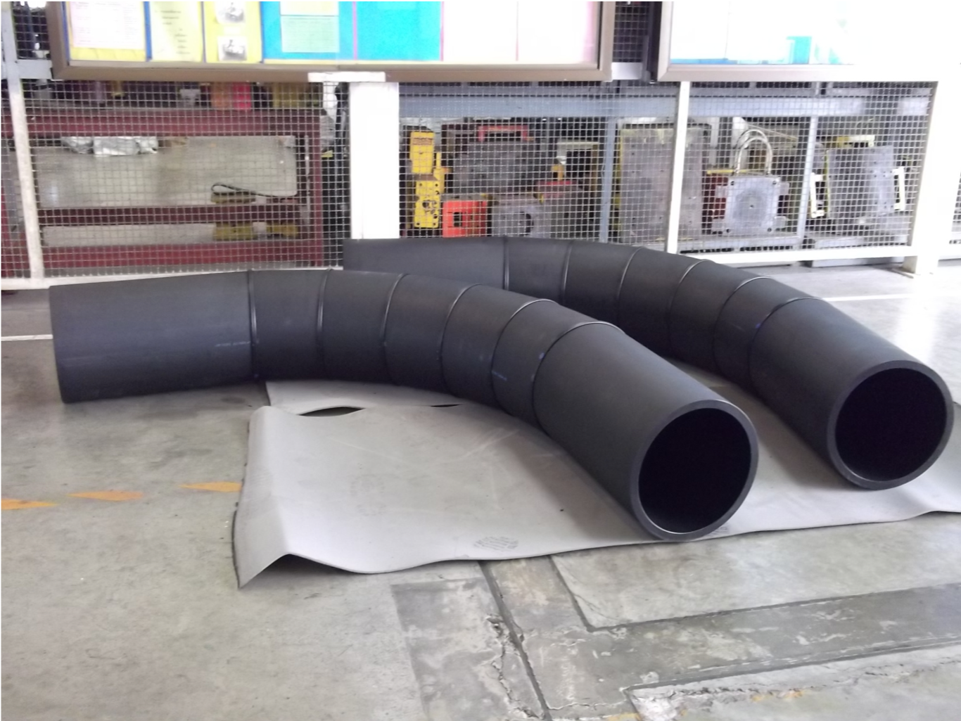
Segmented bends: In larger sizes, these bends are factory-fabricated using the segment design method, as described in BS EN 12201-3 Annex B.3 . Segmented bends are available in any angle and are fabricated using the methodology below